1. Overview
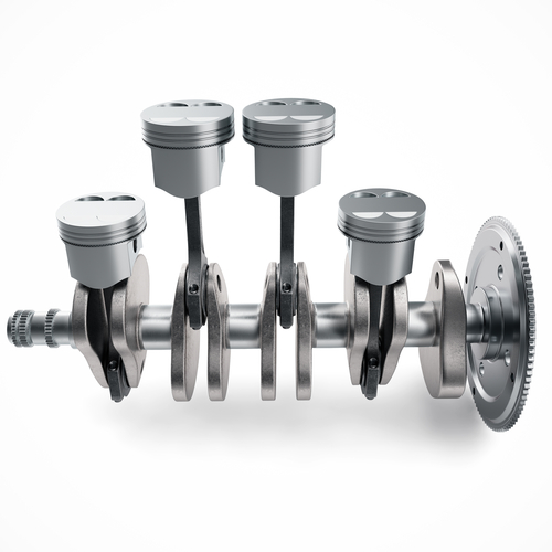
You probably already know that an engine has pistons which convert their reciprocating motion (up and down motion) to rotary (rotational motion) of the crankshaft. The power to turn the crankshaft is made available to the piston by the occurrence of combustion inside the combustion chambers (cylinders) that house the pistons. The combustion event, and therefore the movement of the pistons, must be coordinated to ensure continuous production of power as long as the ignition is on, engine is running, and all other enabling conditions are met. The sequence in which the cylinders generate power is called the firing order, the order in which the cylinders are fired. Most engines today are classified as four stroke engines where stroke refers to the up or down travel of a piston. The four stages/strokes are intake, compression, power and exhaust strokes. Therefore, while one cylinder is on the intake stroke, another is on the compression stroke, another on the power stroke and yet another on the exhaust stroke.
If you’re not familiar with the power transfer process, here is a quick overview. When combustion occurs inside a cylinder, it creates an explosive force that pushes the piston down. This event is called the power or combustion stroke. As the piston is forced down, it turns the crankshaft, the crankshaft turns the flywheel (if vehicle has manual transmission) or flex-plate (if vehicle has automatic transmission). The flywheel/flex-plate then transfers the power generated to the transmission. The transmission finally sends the power to the wheels, causing them to turn. In this article, we will discuss, using examples, what happens during execution of a firing order and why firing orders are necessary.
2. Fire and Order
Choosing the firing order is an essential part of engine design. Manufacturers carefully decide firing orders to tame vibrations and improve heat dissipation. The firing order also impacts ride quality (smoothness of ride), engine balance and engine sound. All these factors, except perhaps engine sound, decidedly play a role in extending an engine’s fatigue life. However, many piston heads consider engine sound an essential part of engine design, understandably so!
Most 4-cylinder engines have a firing order of 1-3-4-2 although other firing orders such as 1-3-2-4, 1-4-3-2, 1-2-4-3 are possible. Consider the inline 4 engine in Figure 1.
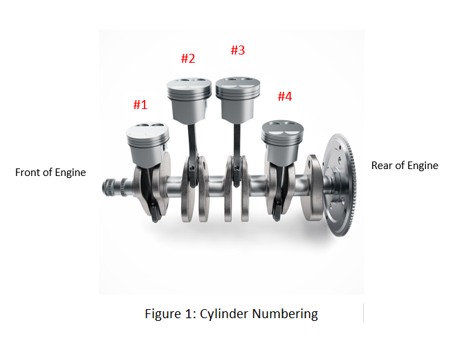
The cylinders are usually numbered 1234 from the front of the engine where the accessory drives (pulleys) are installed. Therefore cylinder 1 will be the cylinder closest to the pulleys and number 4 will be the cylinder closest to the flywheel or flex-plate as illustrated in Figure 1. Let’s assume the engine in Figure 1 has a firing order 1-3-4-2, as is the case on a 2005 1.8 Liter VW Jetta. Since we are assuming a firing order of 1-3-4-2, cylinder #1 will be the first to fire or generate power. Next up will be cylinder #3 followed by cylinder #4 and then finally cylinder #2.
For every 720 degrees the crankshaft turns, the camshaft turns 360 degrees causing all cylinders to fire once. In a 4-cylinder engine such as the one in Figure 1, by the time the crankshaft turns twice, the camshaft would have turned once, firing all 4 cylinders once. Therefore, for every 180 degrees of crankshaft rotation one of the cylinders fire. This is obtained by use of the formula in Equation 1.
f=720/n ……………………Equation 1
Where f is the firing interval and is the number of cylinders.
Based on the formula in Equation 1, in a V6 engine for instance, a cylinder would be fired every 120 degrees. Note however that in some V engines, especially V8 engines and above, manufacturers or engine builders don’t necessarily fire cylinders at regular intervals; this is a concept of engine design called uneven firing. This is done to obtain an aggressive burbling and throaty engine sound. Uneven firing orders will not be discussed in this article.
Before getting into the nuts and bolts of what happens when cylinders are firing, let’s explain the concept of companion cylinders. Companion cylinders are cylinders that move up and down as a pair. While one cylinder is on the intake stroke, the other is on the power stroke and vice versa. Additionally, while one cylinder is on the compression stroke, the other is on the exhaust stroke and vice versa. In a 6-cylinder engine with a firing order of 1-5-3-6-2-4 for instance, the companion cylinders will be cylinders 1 and 6, 5 and 2 and then 3 and 4.
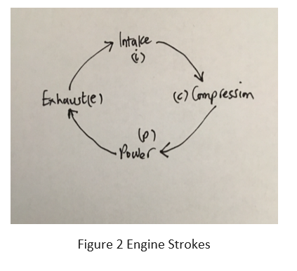
Figure 2 shows the 4-stroke engine cycle in a sequential pattern; intake, compression, power, exhaust. This will be used together with figures 3a through 3e to explain the firing process.
In Figures 3a through 3e, the 720 degrees of crankshaft rotation has been broken into 180-degree intervals to aid illustration.In figures 3a through 3d, the first column contains the cylinder numbers (not in the firing order).
In Figure 3a, cylinder #1 starts off with the power stroke. Since the firing order is 1-3-4-2, it means the next cylinder to fire will be cylinder #3. It follows from Figure 2 that if cylinder #1 is on the power stroke (p) and cylinder #3 is the next to fire, it should be on the stroke before the power stroke because it is preparing to fire after cylinder #1. This is the compression stroke (c) – read figure 2 in a direction opposite to the arrows’ direction, counterclockwise.
Cylinder #4 which fires after cylinder #3 should be two strokes behind the power stroke on cylinder #1. Examining Figure 2 again should help deduce that cylinder #4 should be on the intake stroke (i).
Now cylinder #2 should be 3 strokes behind the power stroke on cylinder #1. That would put cylinder #2 on the exhaust stroke (e). All of this happens in the first 180 degrees of crankshaft rotation (Figure 3a).
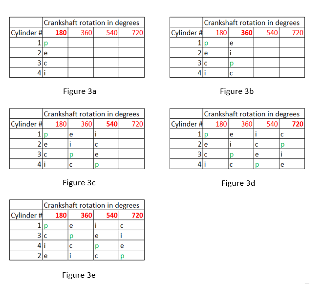
In the next 180 degrees of crankshaft rotation (360 degrees), cylinder #3 enters the power stroke.
Cylinder #4 is now on the compression stroke, cylinder #2 is on the intake stroke (i) and cylinder #1 is, as expected, on the exhaust stroke (e) to expel exhaust gases produced from the power stroke it just completed. See figure 3b.
In the next 180 degrees of crankshaft rotation (540 degrees), cylinder #4 enters the power stroke. Cylinder #2 is now on the compression stroke, cylinder #1 is on the intake stroke (i) and cylinder #3 is, as expected, on the exhaust stroke (e) to expel exhaust gases produced from the power stroke it just completed. See figure 3c.
In the final 180 degrees of crankshaft rotation (720 degrees), cylinder #2 enters the power stroke. Cylinder #1 is now on the compression stroke, cylinder #3 is on the intake stroke (i) and cylinder #4 is, as expected, on the exhaust stroke (e) to expel exhaust gases produced from the power stroke it just completed. See figure 3d.
In the final 180 degrees (720 degrees), notice that cylinder 1 is back on the compression stroke (c) ready to start the entire process again as it moves from the compression stroke to the power stroke (p). Figure 3e illustrates a complete firing order with the cylinders arranged in proper firing order this time. This arrangement makes it easier to see how the cylinders fire every 180 degrees in accordance with the designated firing order.
Figure 4 illustrates the firing orders for a 6-cylinder engine with firing order 1-4-3-6-2-5. This is the firing order on the Mercedes Benz M272-E35 engine which has powered ML350 vehicles since 2006. It also powers the R350 vehicle and other Mercedes Benz vehicles.
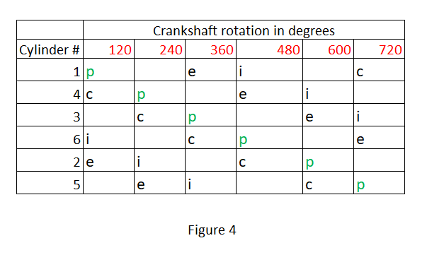
From figure 4 cylinder #1 fires in the first 120 degrees.
In the next 120 degrees (240 degrees), as cylinder #1 moves from the power stroke to the exhaust stroke, cylinder #4 fires.
In the next 120 degrees (360 degrees), as cylinder #4 moves from the power stroke to the exhaust stroke, cylinder #3 fires.
In the next 120 degrees (480 degrees), as cylinder 3 moves from the power stroke to the exhaust stroke, cylinder # 6 fires.
In the next 120 degrees (600 degrees), as cylinder 6 moves from the power stroke to the exhaust stroke, cylinder # 2 fires.
In the next 120 degrees (720 degrees), as cylinder 2 moves from the power stroke to the exhaust stroke, cylinder # 5 fires.
The process repeats as cylinder #1 fires again.
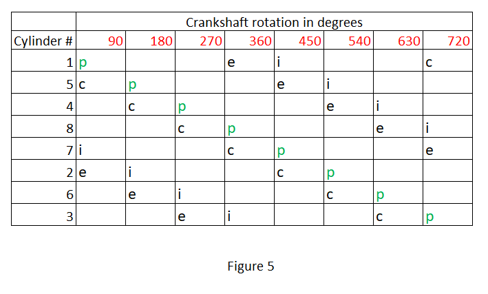
Figure 5 is a tabular illustration of an 8-cylinder engine with firing order 1-5-4-8-7-2-6-3. An example of an engine that uses this firing order is BMW’s S65 which powers the 2012 M3 E90 among other vehicles. Figure 5 will not be explained further as it follows a similar format to the order explained previously in Figure 4. The only difference is that each cylinder will fire after 720/8=90 degrees.
Share your thoughts.

Author:Kwabena Mensah
About Author:Technical Editor and CTO at AutoShack Ghana
